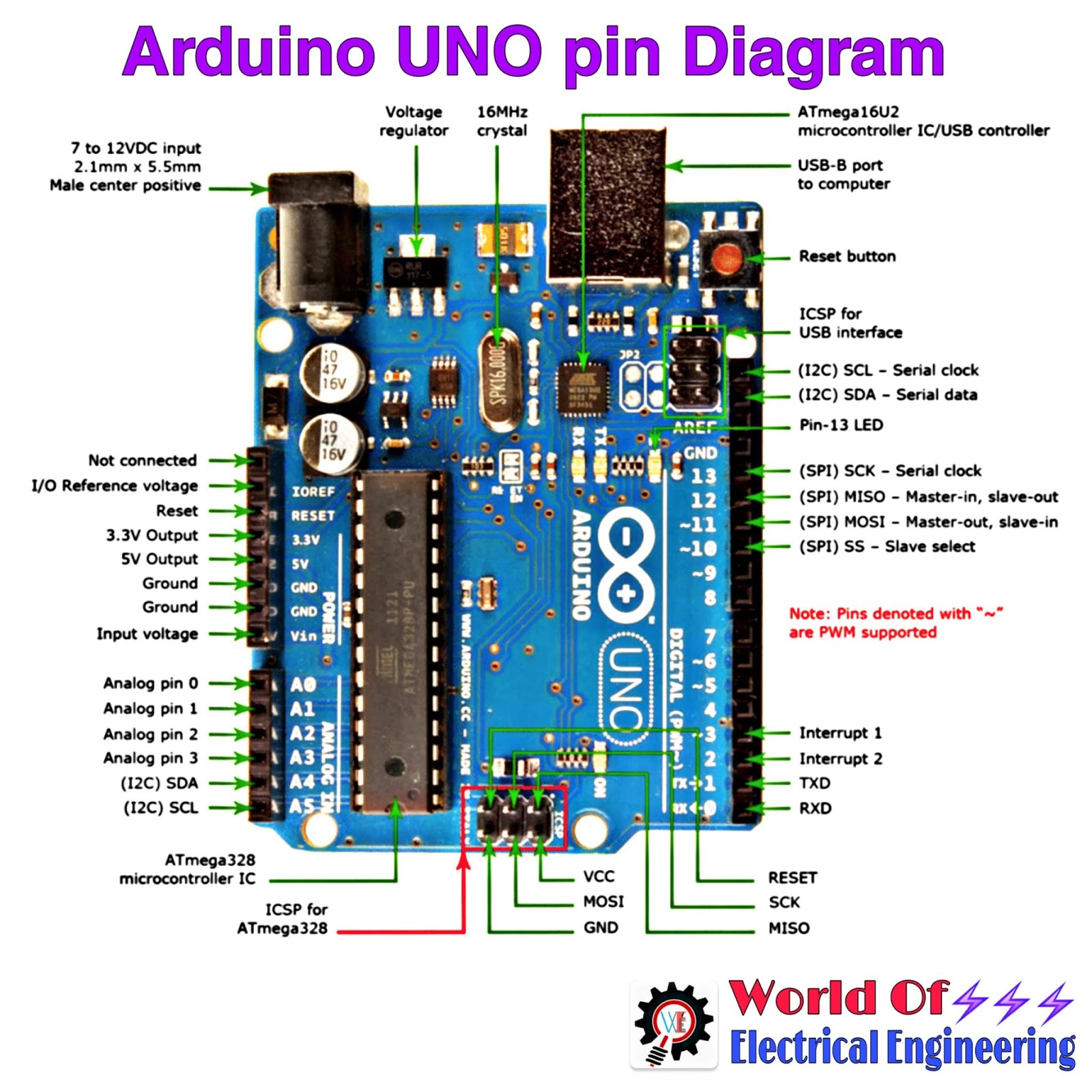

Whether you’re a hobbyist, student, or serious designer, using an Arduino board as the backbone for your next PCB is a great way to break into new areas of electronics design. string senderMsisdn: MSISDN to send to.A heavily rules-driven PCB design platform for designing the best PCBs.int channelNo: GSM channel number, 0 to 7, this channel will be used as sender.SendSms channelNo destinationMsisdn "SMS text" Available commands:Ĩ status objects, one per GSM channel (see status command) The firmware uses Serial interface to communicate with host computer, the commands follows a simple text protocol, one command on each line and with following structure:Ĭommands response are valid JSON objects. The firmware is under the firmware folder, you can use Arduino IDE to mod or add new features.

This part has been designed to support the 8 Bnc antennas, fitting in any ATX case back side.

GSMPWR: GSM modules power: connect, from left to right: ATX Red (5V), ATX Black (GND).LPWR: Logic power: connect, from left to right: ATX Purple (5V SB), ATX Black (GND).ATXE: ATX enable signal, connect, from left to right: ATX Black (GND), ATX Green (Enable).RSW: reset switch, connect the ATX reset switch.PSW: power switch, connect the ATX power switch.

Board designed using Eagle Cad, sources under hardware folder. The device is based on an Arduino PRO mini, running at 16 MHz and 5V. This repo contains source code and hardware specifications for building a 8 SIMs communications device to monitor SMS reception on up to 8 mobile lines.


 0 kommentar(er)
